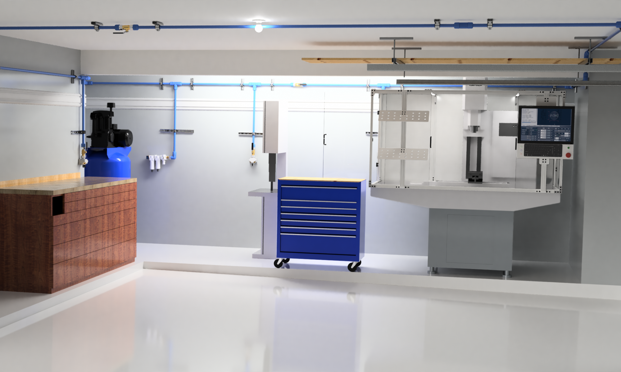

A two car garage is not as big as you might think. Particularly if you intend to put two cars in it when you aren’t working in it. And if you live on the Texas Gulf Coast, it’s hot and humid in the summer and cold (and humid) in the winter with hardly any days when it’s actually comfortable. Add to this that you need good light if you want to do anything (this is still a work in progress for me).
Residential garages are not like bespoke shop buildings. They have low ceilings, garage doors (and door tracks) with short openings, steps, and things like attic accesses that need to be available, limiting the available floor space. And you simply do not have floor space if you want to keep a car in it.
Another problem is that your typical garage floor is made of very porous, dark gray concrete that does nothing better than absorbing everything that comes in contact with it, including light. (A gray hole?)
Solving all these problems is going to be dependent on your situation, but there are some common threads that my experience may be helpful with.
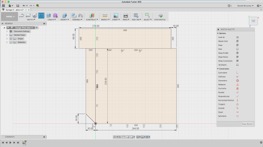
The place to start is the floor plan. Measure everything. Be accurate and pick up on details. Below is a floor plan based on my garage measurements (it’s not exact, since this is an example).
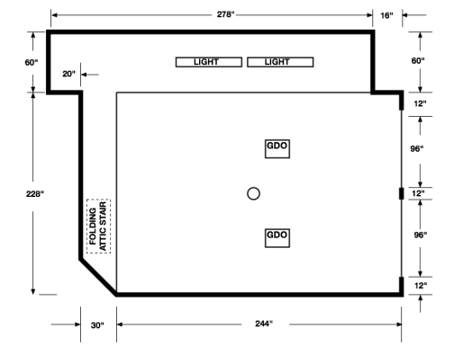
While the picture above was created in Autodesk Graphic, the original sketch was made in Autodesk Fusion 360 with some slips of paper used to gather the dimensions to generate a 3D model. Primary tools to make these measurements were nothing more than a pen, paper, and a tape measure.
Keep in mind that you don’t need computer design programs to capture this floor plan. A pencil and a piece of graph paper will do quite well for 2D layout of the space.
Now if you’re looking at that floor plan and think that’s a lot of space, let me disabuse you of that notion. For this project, I set a couple ground rules:
- There will always be room on the floor for two cars. If anything takes up space in a car bay it MUST have a place to go when not in use.
- Nothing is stored on the floor unless it can be rolled away to use the space for something else (exceptions are anything that is too heavy to move or requires re-leveling after being moved)
Ground Rule 2 sounds like a challenge, but the fact is, if you don’t have space to work in, you don’t have a shop. You have instead a storage space that you happen to use for making things. By requiring that storage be movable, you preserve your effective floor space. If I have a project that needs the whole garage, all I have to do is move the car(s) outside and reorganize what remains to leave room for my project. For things that can’t move, they had better earn their keep.
How you choose to organize your shop is up to you. This series will attempt to follow some of the guidelines of the Kaizen/Lean manufacturing theory to make the best use of the limited space available. We’ll talk about Lean more later – but keep in mind that the goal here is to keep the clutter down and always be able to find things quickly.
Going back to the floor plan, you can see that there are some obstacles in the floor itself. The two car bays are on a slightly tilted slab (intentionally, so it drains) that sit from 4 to 6″ below the level of the house floor. This presented an enormous problem in working out where to put machine tools, i.e., the level areas are the only place to put them. (Since Ground Rule 1 says the car bays have to be open anyway, this is less of a hardship, but is part of the reason why the rule exists in the first place.)
The next problem is figuring out where everything has to go. Not including items needing storage (a much different problem), in my situation there had be places for the following:
- 80×30 Workbench/cabinet
- PCNC 1100 Mill
- 80 gal stand compressor (there will be a post on this)
- 10″ Siding Compound Miter saw (on stand)
- 16″ woodworking bandsaw
- floor standing drill press
- floor standing scroll saw
It should be no surprise that over a year later, the bandsaw, drill press, and scroll saw are still not back in the garage… Not that there isn’t space, but as soon as they’re in place, there will be no room to maneuver. They all need to be made mobile, and that’s another project.
The real problem comes from trying to visualize each machine in the space. You can do it in 2D, like this:
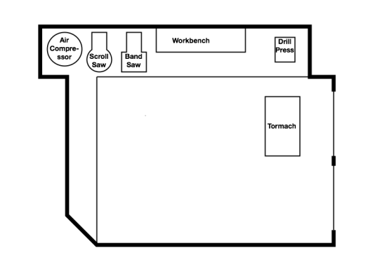
This arrangement, which among other things violates Rule 1, makes poor use of the space available. Presumably the space along the left wall could be used for storage with shelving or cabinets.
The trouble is that most people will have a hard time visualizing how this will actually work. Where do materials come in? Where can things be stored? There’s no sense of vertical space, which turns out to be very useful in making space for everything. And what the heck do you do with that beam that runs across the opening to the garage extension?
So how to add another dimension? 3D CAD, of course, specifically Autodesk Fusion 360. For those of you not familiar with this tool, Fusion is an easy to use 3D CAD/CAM/Simulation environment that is offered free to hobbyists and low cost to business users making over $100K/yr.
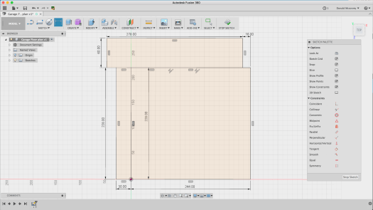
So the way to begin is with a sketch. Once you have a copy installed on your computer, Open Fusion 360, and as soon as you have the window open, create a new project and save the file (this guarantees that F360 will keep a recent copy in the event your system crashes for some reason):

Now create a sketch on the XZ plane by clicking on the two-point rectangle on the ribbon, selecting the XZ plane on the workspace and laying out a rectangle for the car bays:

Add more rectangles for the other areas you measured – for this model the Workshop Extension and the raised step at the back of the garage.
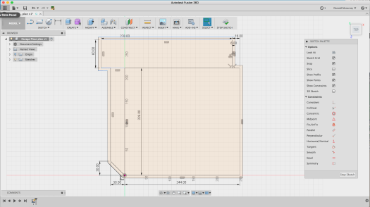
And if you go back to look at the original flat sketch, you’ll see that there are details for the garage doors, walls, and the diagonal doorway on the lower left. The latter is created by removing the Horizontal/vertical constraint, and then moving the corner 30″ upward to create the angled doorway:
Creating the outer walls is done by selecting each wall segment and then using the “offset” command (under the “Sketch” menu) to create an outline that is 6″ thick. The offset requires that you break up the horizontal line between the top rectangle and the two lower ones so that the entire perimeter can be selected. Just select those lines, delete them, and then replace them one at a time using the Line command:

In this case, you want to ensure you keep the line for the step between the car bay and the workshop extension

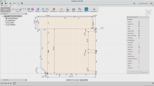
Now select all the line segments that make up the perimeter of the space and use the offset command to create the outside wall:
The two garage doors are 96″ wide, and since we don’t need a super-accurate model of them, we just create rectangles in those spaces and delete the wall in those locations (you’ll find you need to patch up the lines for the outer wall – do this with the line tool):
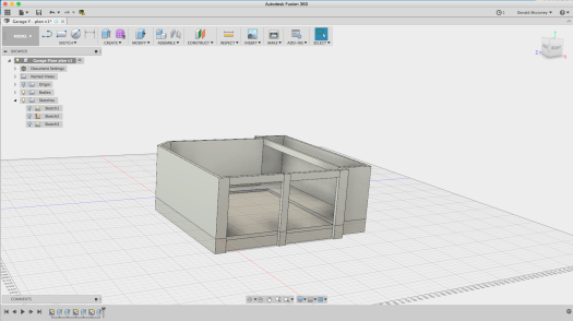
At this point you can stop the sketch by clicking “Stop Sketch.” This is enough to create a solid model for the floor and the walls, which is all you really need for layout.
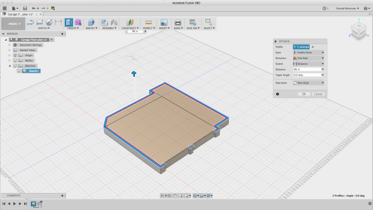
From here, we create the solid model by selecting the whole floor, then using the “extrude” command to create the foundation, which is arbitrarily made 24″ thick, going in the negative direction:
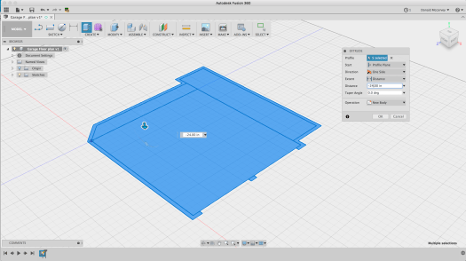
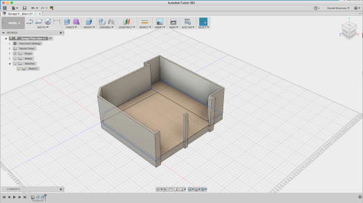
You’ll need to show the sketch again – so click the arrow next to the “Sketches” item and then click the light bulb button to turn the sketch back on. Select the walls and extrude them 8′ – but make sure to create a “new body” – you’ll want to be able to remove them from time to time to get a better view:
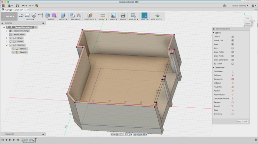
The garage door openings aren’t that tall – they’re only 7′ – so we need to create another sketch which will allow us to create the headers over the doors. We’re also going to create the sketch for the ceiling, though we won’t use it just yet. To quickly create the ceiling, use the “project” command and select each outside wall face, including the post between the garage doors. To create the profiles needed to make the header over the doors, you draw rectangles that touch the corners of the walls and the center post as you can see below.
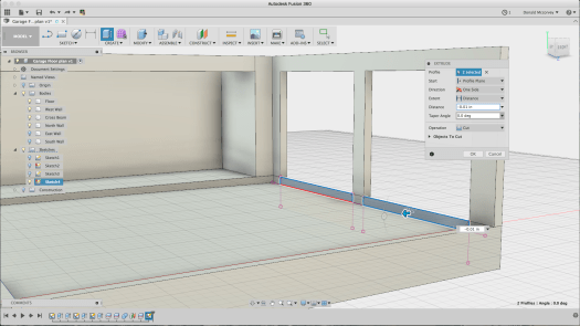
Before we create the headers, there’s a beam across the opening to the workshop extension which holds up the roof above. Since you should model all the constraints in your space, this is a good thing to include – and one of the reasons a 3D model is useful:

Now we can create the headers over the garage doors and the cross beam at once by extruding all three rectangles:
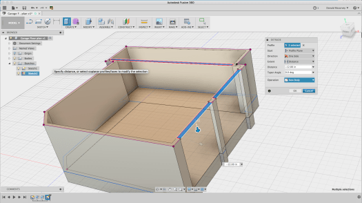
Note that these were created as a new body, not a join – this will change shortly.
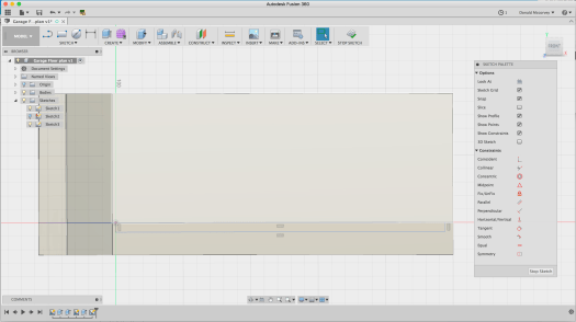
My garage has a challenge because of the sloped slab in the car bays. It’s 6″ below the floor level at the front, and 4″ at the back. To create this, we need another sketch, but this time, it’s going to be on the XY plane through the origin. You do this by selecting the XY plane when you’re prompted to choose a sketch plane. Since the wall is in the way, rather than selecting the wall face, hold down the mouse button over where the yellow XY plane is visible and a popup menu will allow you to choose any face or reference plane under the mouse cursor

Once you’ve created the sketch plane, draw a rectangle from the origin to the inside of the wall at the front by touching the line where it intersects with the sketch plane and then draw out a rectangle:
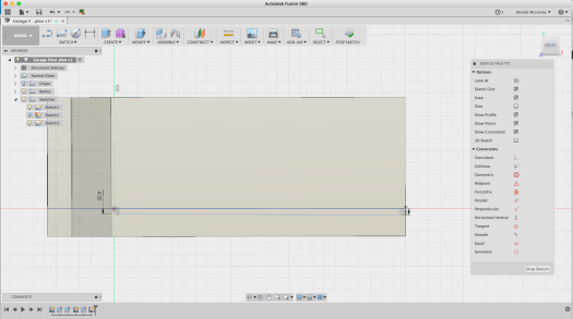
Now, delete the horizontal constraint – the two parallel lines on the bottom line of the rectangle, then dimension the two ends to 4″ and 6″ as shown below:
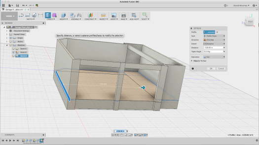
Now extrude the sketch profile 228″ to cut away the floor and create the sloped car bay:
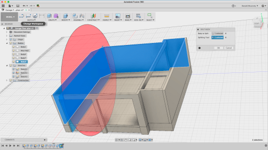
You’ll want to do a few more things to make the model work well. One of which is being able to remove walls when you want to. We’re going to split the model into four pieces: North Wall, South Wall, East Wall and West Wall, naming each of the bodies we create accordingly.
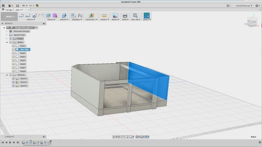
This is very easy to do, but perhaps not obvious. The west wall is simple: Go to the “Split body” tool under the “Modify” menu. Select the wall body, then select the inside of the west wall (that’s the one on the right side in all the pictures above) as the cutting tool:
Now find and rename the body in the browser to “West Wall” to make it easier to identify:
You’ll discover that most of the front wall is already cut from the rest, but let’s make it one whole unit. Use the same splitting tool to pick up the left side of the garage opening:
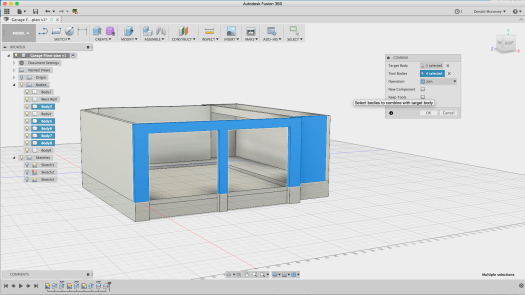
Then join the pieces that make up the front wall using the “Modify->Combine” command
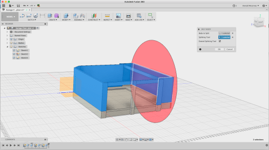
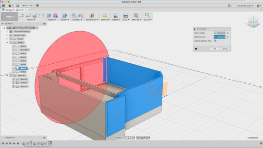
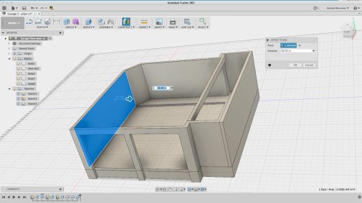
Finally, we need to split the east wall from the South wall. This is a little more difficult. Create a construction plane (Construct->Offset Plane) that is offset from the inner wall by 30″ so that it cuts at the edge of the doorway:
Now use it to cut the wall body using the Split (Modify->Split) command:
Hide the construction plane, then finish the job by renaming all the bodies to their new names by selecting them to identify which body it is, then double clicking the name in the browser to edit and change them to East, South and North walls, respectively. Also identify the Floor and the Beam bodies.

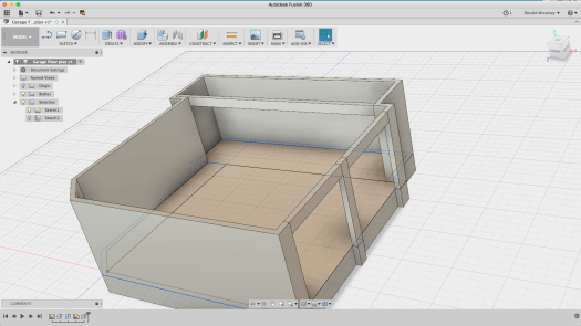
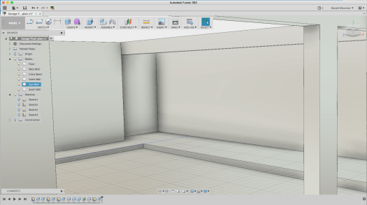
Now, you can rotate the model around and view it from various angles, removing walls as necessary to get an eye-height view of the space:
Notice that there are some residual segments of the floor at the garage door opening. This can be removed by creating a sketch on that plane, using the “Project” command to create the profile and extruding it to cut it away:
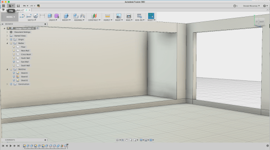
And here’s the finished product, looking from the left side of the left garage door opening:
You may be thinking: “What about the ceiling?”
Right now, lighting the model becomes a problem if you put in the ceiling and for the moment, you can live without it. Adding the ceiling becomes necessary later if you start hanging things from it and want to add lighting so you can get an idea how the space looks before you’ve spent any money on it.
For now, you can begin to see the available volume – and in some respects, how little there really is. Sure, the floor is open, but it’s usually filled with at least one car, and by Rule 1, there needs to be space for two. There’s a little unused space under the attic stair which we’ll add later, but that’s all the space there is.
Of course, you’re looking at plenty of other opportunities. If the floor is mostly off limits, then only those things that simply must reside on the floor are allowed to do so. Everything else has to be on the walls or hanging from the ceiling if it isn’t up in the attic (which is a limited space as well).
Ceiling space in particular is an underused resource. The space above a garage door, for example, is totally wasted, unless you have something somewhat long and flat that can be put there. The space above the compressor is similarly available (and not yet in use as of this writing – but it will be eventually).
Look at the space between the right garage door and the projection wall adjoining it in the floor plan. What might fit in that space? Bar clamps of many sizes will likely find a home there. A surveyor’s tripod is currently residing there and probably will continue to.
And consider what else you’re needing to reserve space for. For example, at multiple locations you’re likely to want a general-purpose air hose. You will not want that on the floor, so it needs to hang from somewhere. Punching holes in the walls for hooks means messing up the walls you probably just spent days patching up, so finding ways to use that wall space without dinging them up is worthwhile. (If you have a big budget, you might consider a slatwall system. With a more moderate budget, a partial slatwall will look better and be easier to keep clean than pegboard.)
Here’s another one that still isn’t solved: What to do with small parts? If you’ve been to the hardware store lately, all those screws and nuts and other fasteners add up quickly to a lot of cost. Throwing them out isn’t sensible, but storing them in a way that they can be usable is difficult. There are a number of ways for industrial storage of such parts, but they tend to be oversized and take up a lot of space (ACRO bins come to mind). Little chests of drawers are another answer, but they tend to become disorganized and are hard to see into. Another solution will get covered down the road a bit.
Lastly, consider cleaning this space in the future. My garage was built with drywall on the walls. With a fresh coat of paint, and the epoxy coated floor, it’s easy to clean if you can keep the clutter under control. It also means you have more light being reflected about and brightening the whole space. Dark, roughed-in walls are inexpensive, but they are hard to clean and easy to get filled with dirt and dust as well as other stuff that gets permanently stored there. So covering up those stud bays while not cheap, has some advantages.
Next time: Selecting and putting in a floor system
